
This post is part of a series in which I am following the structure of J. Clark Scott’s book But How Do It Know? (Affiliate Link – commission supports my knowledge quest). You can check out his website at http://www.buthowdoitknow.com/ (not an affiliate link). It’s written with no assumption of knowledge or background, which has been great for me 😉
CPU/RAM Communication – An Elevator Pitch
The CPU and RAM of a computer communicate using system of wires, called a bus. This bus usually has three parts, the address bus, the control bus, and the data bus. Since RAM holds data, and CPU performs some action (processing) on the data, the CPU first sends and address to RAM by turning on (I use “lighting”) wires to indicate (in binary) an address number. It then uses the control bus whether it’s reading from, or writing to, RAM. Finally, if it’s reading from, RAM will send the data across the data bus. If it’s writing to RAM, the CPU sends processed data back to RAM using the same data bus.
A Cook in the Kitchen
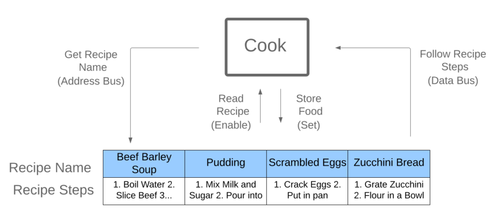
I see quite a few explanations made on the relationship between CPU and RAM, usually they are likened to the human brain. I suppose that works, but what helped me understand the basics of this communication was thinking of a cook retrieving and following recipes in the kitchen. It’s an OK analogy, although you probably wouldn’t store food in a cook book. So pretend this cook’s cookbook is really magical.
- Get Recipe -> Address Bus.
- Read Recipe or Store Food -> Control Bus
- Follow Recipe or Place Food in Cookbook (magic) -> Data Bus
The cook will follow the basic 3 steps above. First she finds the Scrambled Eggs recipe by its name (they’re in alphabetical order, of course). Then she decides whether she wants to read the recipe, or store some eggs she just made according to the recipe. In this case, she’ll read it. Finally, she follows the recipe and makes Scrambled Eggs.
In my diagram of a simple CPU, the buses are arbitrarily 2 bits wide and the number of address slots in RAM are 4, mostly because I ran out of room and 4 seemed like a nice easy number. In reality, you would have many, many more slots and bus wires.
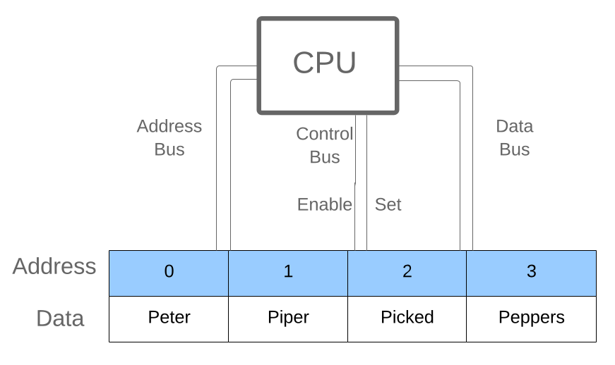
1. Address Bus
The CPU first sends an address to RAM using the address bus wires. Each wire represents a bit (a 1 or a 0). In this example there are 2 of them, for a total of 4 possible addresses (00, 01, 10, and 11). If the CPU wants the contents of RAM address 2, it would light up the first wire and keep the second dark to represent 10, or 2 in binary. RAM would send the letter “Picked”, as requested, across the data bus if the Enable wire is lit. Or if the set wire were lit, data would be written to RAM’s data in the 3 slot, perhaps something like “A Peck”.
2. Control Bus
This controls receiving and sending. Enable means “receiving”, set means “sending”. You can also think of this as read or write. In my simple CPU above, lighting the enable wire transfers data from RAM to CPU, lighting the set wire writes data already processed by the CPU to RAM.
3. Data Bus
This is where all the goods are stored in binary. I just picked some funny words to represent data because it seemed like a nice way to illustrate the point, but the data could be anything. Every kind of data out there has some interesting way of encoding it. For example, letters use a system called ASCII or Unicode to translate letters to binary. Pictures use a variety of formatting, like JPEG or PNG, etc. But it’s all binary in a computer.